Solidworks How to Open Simulation Again
This tutorial demonstrates how to set up and design movement simulations using NI SoftMotion for SolidWorks. Utilize an NI LabVIEW project to connect to a preconfigured SolidWorks movement study, create and configure NI SoftMotion axes for the motors in the SolidWorks assembly, and use NI SoftMotion function blocks to create a trajectory for the SolidWorks simulation. This document covers how to use NI SoftMotion function blocks with your existing SolidWorks assemblies to create and evaluate motion profiles for your system. For information nigh using SolidWorks, refer to the SolidWorks documentation.
To accomplish the interfacing of SolidWorks with NI SoftMotion and LabVIEW, the tutorial will go through the following steps:
- Setting Up the LabVIEW Projection
- Configuring the Axes
- Creating a Movement Profile and Running the Simulation
- Deploying, Running, and Stopping the Simulation
Required Software and Hardware
The following software is required for this tutorial.
- LabVIEW 2009 (32-fleck) or later
- LabVIEW NI SoftMotion Module Standard or Premium
- SolidWorks 2009 Service Pack ii.1 or later
- SolidWorks Motion Simulation with the Motion Simulation add together-in enabled from theToolsmenu in SolidWorks.
This is included with SolidWorks Premium, Simulation Premium, or Simulation Professional. When you lot enable the Motion Simulation add-in from theAdd-Ins dialog box in SolidWorks, place a checkmark in both the left and right checkboxes so yous don't have to reenable the add-in each time yous utilize NI SoftMotion for SolidWorks. You tin download a free 7-solar day trial of the required NI software from ni.com/labview/family unit.
The following additional hardware and software is required to complete the "Pace 4: Deploying to Hardware (Optional)" section of this tutorial:
Software
- LabVIEW Real-Time Module 2009 or later
- NI-RIO 3.2.0 or later on
Hardware
- NI CompactRIO controller and chassis that back up the RIO Scan Interface
- OR NI 9144 distributed chassis
- Two NI 9512 unmarried-centrality stepper bulldoze interfaces
- Power supply for the controller
- A separate power supply for the modules
- Ethernet connectedness and cable
Fifty-fifty if you practice not have the hardware used in this tutorial, you can follow the steps and perform offline configuration to larn virtually using CompactRIO with LabVIEW.
Overview of NI SoftMotion for SolidWorks
Past using NI SoftMotion with SolidWorks to simulate your system with actual movement profiles, you can simulate mechanical dynamics, including mass and friction effects, cycle times, and individual component functioning, earlier specifying a single physical function and connecting it to an actual command algorithm. Virtual prototyping (also known as digital prototyping) offers you the power to visualize and optimize the pattern and evaluate different design concepts before incurring the cost of physical prototypes. Integrating motility simulation with CAD simplifies pattern considering the simulation uses information that already exists in the CAD model, such as assembly mates, couplings, and material mass properties. LabVIEW provides an easy-to-use, high-level function block programming language for programming the motion control organisation that is simple enough for users with little or no previous move control programming feel. Typical applications for the LabVIEW NI SoftMotion Module with NI SoftMotion for SolidWorks include the following:
•Motion trajectory pattern — You can build complex motion profiles containing a serial of sequential or concurrent move operations composed of multiaxis straight-line moves, contoured moves, arc moves, and even complex moves using electronic gearing and camming.
•Visualization — Past animating your 3D SolidWorks assembly using the motility control profiles and timing/sequencing logic yous take designed in LabVIEW, you lot can quickly evaluate the feasibility of the overall conceptual design for your machine. Visualizing the working car as a virtual epitome helps to validate the overall conceptual design for the auto very early in the evolution. This fosters meliorate communication with customers and betwixt design team members and helps to close the loop on the design requirements, must-have features, and engineering trade-offs.
•Standoff detection — With the standoff detection feature in SolidWorks, y'all tin can validate your motion profile designs using your actual 3D CAD model. You can check for interferences, evaluate the need for interlock control logic to prevent collisions, optimize your motion profiles to minimize unnecessary dead time, quickly evaluate what-if scenarios, and safely exam new control system logic without the risk of damaging your physical car. After y'all have designed, prototyped, and deployed your machine to the field, you tin too use collision detection to validate new motion profiles earlier downloading them to machines operating at your client site. This reduces the risk of unplanned reanimation due to programming mistakes.
•Throughput time studies — By validating your motion arrangement blueprint using a simulation that includes the bodily move profile constraints and the mechanical dynamics of your machine such equally mass and friction, you can accurately summate an estimate for the cycle time throughput of your automobile.
• Motor, bulldoze, and transmission sizing — Motor torque and velocity requirements depend on the acceleration characteristics of your motion profile and the mechanical dynamics of the payload and manual components such as lead screws. Using NI SoftMotion for SolidWorks, y'all tin calculate the required motor torque and velocity charts for your motion profiles.
Step 1: Setting Up the LabVIEW Projection
Before you tin start designing motion profiles for your SolidWorks simulation, y'all demand to import the information from your SolidWorks associates into the LabVIEW Projection and create NI SoftMotion axes for the imitation motors included in your associates.
Calculation the SolidWorks Assembly to the Project
Complete the following steps to add the SolidWorks assembly to the LabVIEW project:
i. Launch SolidWorks and open up theSorting Machine.SLDASM file from the<labview>\examples\Motion\SolidWorks\SolidWorks Files directory. Upon opening the model, navigate toOptions»Add-ins and ensure that the SolidWorks Motility and SolidWorks Simulation add together-ins are active. Next, select theMotion Study one tab in the lower left corner and ensure that the Motion Study type pull-down is set toMotion Analysis, as shown in Figure 1.

Figure 1. SolidWorks Motion Written report Setup
This model simulates an assembly that takes test tubes from one location and moves them to another and the tutorial focuses on using an arc move to movement the test tubes to a rotary tabular array. At this point, the assembly and motion study must exist set up to simulate with all the constraints and motors properly configured. Refer to the SolidWorks Help for more than information nearly setting up a SolidWorks assembly.
two. Open an empty LabVIEW Project and right-click theMy Estimator item in the LabVIEWProject Explorer window and selectNew»SolidWorks Associatesfrom the shortcut carte to open up theImport SolidWorks Motors from Assembly File dialog box.
3. Select the SolidWorks assembly to add to the LabVIEW projection. If a SolidWorks associates is currently open, theImport Axes from Associates File dialog box contains the path of this associates. ClickBrowseto select a dissimilar assembly file if necessary.
4. ClickOK. The selected SolidWorks assembly is added to theProject Explorer window, including all motors contained in the SolidWorks move study.
If the SolidWorks assembly contains multiple motion studies, cull the motion report to add to the projection using theSelect Move Studydialog box. To change the motion study used in the project after adding the assembly, right-click the SolidWorks associates particular in the project tree and selectChange Motion Report... from the shortcut menu. Figure ane shows theProject Explorer window with a SolidWorks associates added:

Figure 2. SolidWorks Assembly in the LabVIEW Project
5. Correct-click the SolidWorks associates in the Project Explorer window and selectPropertiesfrom the shortcut menu to open theAssembly Backdropdialog box. In theData Logging Propertiessection, specify a name for the log file and place a checkmark in theLog Datacheckbox and selectOK. This logs position, velocity, dispatch, and torque data for the simulation to the specified file proper noun in LabVIEW Measurement (.lvm) format.
Each simulation overwrites the selected log file. To create a new log file for the adjacent simulation, yous must change the file proper noun earlier starting the simulation.
Adding Axes to the Project
To simulate using the SolidWorks motors included in the model, you lot need to acquaintance the motors with NI SoftMotion axes. The NI SoftMotion axes are used when creating motion profiles with the NI SoftMotion part blocks. Complete the post-obit steps to add together NI SoftMotion axes to the project:
one. Correct-click theMy Calculator item in theProject Explorer window and selectNew»NI SoftMotion Axis from the shortcut menu to open up theAxis Manager dialog box.
two. SelectAdd New Axis. The new axis automatically binds to an bachelor SolidWorks motor.
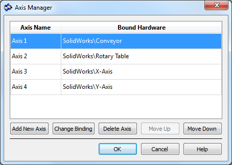
Figure 3. Centrality Manager Dialog Box
3. ClickAdd New Axisuntil all available SolidWorks motors are associated with NI SoftMotion axes.
iv. Double-click the Centrality Name of each axis to rename the axis more descriptively (e.g., Conveyor, Rotary Table, Ten Axis, Y Centrality).
5. ClickOK. All axes are added to theProject Explorerwindow as shown in Figure 4.

Figure four. Project Explorer Window with a SolidWorks Assembly and NI SoftMotion Axes
Adding Coordinates to the Project
You can group NI SoftMotion axes into coordinate spaces so that y'all tin perform coordinated moves using multiple axes simultaneously. Apply the coordinate spaces every bit inputs to your motility applications when performing coordinate moves. Complete the following steps to add a coordinate space to the project:
one. Right-click My Computer in theProject Explorer window and selectNew»NI SoftMotion Coordinate Space... from the shortcut menu to open theConfigure Coordinate Space dialog box shown in Effigy 4.
2. MoveX Centrality andY Axis from theAvailable Axes column to theCoordinate Axes cavalcade using the arrow as shown in Figure 5. If desired, double-click the coordinate space name to rename the coordinate infinite and give it a descriptive name.
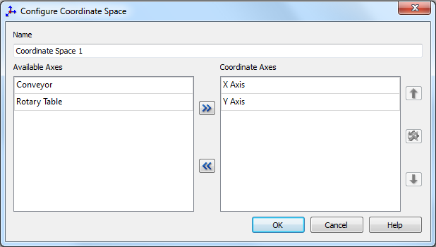
Figure 5. Configure Coordinate Space Dialog Box
iii. ClickOKto close theConfigure Coordinate Spacedialog box and add the new coordinate space to the LabVIEW project. Your project is now set up with the axes and coordinate spaces you need for the application. Your LabVIEW project should expect similar to Figure 6.

Figure half-dozen. LabVIEW Project with NI SoftMotion Axes and Coordinates
When using coordinate resource, target position and other information are independent in a 1D assortment with axis information provided in the society that axes are added using this dialog box.
Step 2: Configuring the Axes
Axes associated with SolidWorks motors are assumed to be servo motors. Because the axes are not associated with actual hardware, you need to perform only minimal configuration to become started. Once you have fix your simulation, you tin can change configuration settings on the axes for easy deployment to the final hardware using the profiles y'all create. Complete the following steps for the 10 Axis and Y Axis to configure the axes for apply in your simulation:
ane. Correct-click the centrality in theProject Explorer window and selectPropertiesfrom the shortcut menu to open theAxis Configurationdialog box. Figure 6 shows the parts of theCentrality Configurationdialog box for SolidWorks axes. Items that are not applicative to your configuration are greyed out.

Effigy vii. Axis Configuration Dialog Box for NI SoftMotion for SolidWorks Axes
ii. On theAxis Configurationpage, ostend that theCentrality EnabledandEnable Drive on Transition to Active Manner checkboxes contain checkmarks. This automatically activates all axes when the NI Scan Engine switches to Active style. (Yous tin also employ the Power function block in your Half dozen to activate and enable axes.)
3. ClickOKto close theAxis Configurationdialog box. Make certain to perform steps one-3 for both the 10 Axis and Y Axis SoftMotion Axes.
Step three: Creating a Motion Contour and Running the Simulation
You create motion profiles for simulation with the SolidWorks associates using the NI SoftMotion function blocks on theNI SoftMotion»Advanced»Office Blockspalette. With these function blocks, you can perform direct-line moves, arc moves, contoured moves, gearing and camming operations, and read status and data data.
Configuring the Timed Loop
A Timed Loop synchronized to the NI Browse Engine allows your time-sensitive motility applications to execute at the browse rate. Whatsoever code placed inside a Timed Loop is guaranteed to execute once per scan menstruum or at an interval you specify. You should minimize retentivity allocations in Timed Loops to avert introducing jitter into the system. NI SoftMotion office blocks are typically used on hardware running a real-time OS to create deterministic motion command applications using the role block programming prototype. When y'all employ NI SoftMotion part blocks on Windows with a SolidWorks simulation, the timing of the NI Scan Engine is non guaranteed.
If your code does not need to run at the scan rate, you tin can apply a while loop with a Wait Until Adjacent ms Multiple function to control the loop rate. Complete the post-obit steps to configure the Timed Loop:
i. Correct-clickMy Computer and selectNew»6 from the shortcut carte du jour to open up a bare VI.
2. Identify a Timed Loop on the block diagram of the VI. The Timed Loop is located on theTimed Structures palette.
three. Double-click theInput Node of the Timed Loop to open theConfigure Timed Loop dialog box.
4. UnderLoop Timing Source, forSource Type, selectSynchronize to Browse Engine. You tin click theAssistancebutton for information near synchronizing to the NI Browse Engine. TheConfigure Timed Loopdialog box should look similar to Figure 8.
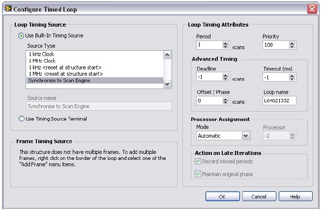
Figure 8. Configuring the Timed Loop
5. ClickOK.
Creating a Movement Profile
This example uses the NI SoftMotion Arc function cake with the NI SoftMotion coordinate resource to perform a circular arc motility to movement the test tube.
Complete the following steps to set upwards the arc move:
1. Place anArc Move function cake from the SoftMotion Function Blocks palette inside the Timed Loop.
2. Right-click theexecuteinput and selectCreate»Control from the shortcut menu to add a control to the front end console for this input. Repeat this step for theradius, beginning angle, travel angle, velocity, andaccelerationinputs and selectCreate»Commandfrom the shortcut menu to add controls to the front panel for each of these inputs.
3. If desired, additional parameters such as deceleration and jerk can be added by double-clicking theArc Move office block. In theArc Motility Part Block Properties dialog box, select theVisible? check box and gear upInformation source toLastfor any additional parameters. ClickOKto finish the configuration.
4. Right-click thedoneoutput and selectCreate»Indicatorfrom the shortcut menu to add an indicator to the front panel.
five. Drag theCoordinate Space one resource from the LabVIEW Project on the block diagram outside the Timed Loop and wire it to theresourceinput on the function cake.
half-dozen. Right-click themistake out output and selectCreate»Indicator from the shortcut carte to add an indicator to the forepart console.
7. Wire thefault outoutput to the edge of the Timed Loop.
8. Right-click the loop tunnel created for theerror out output and selectReplace with Shift Annals from the shortcut menu. This transfers the fault data to the next loop iteration.
9. Wire theerror ininput of theArc Move role block to the shift register created on the left side of the Timed Loop.
10. Right-click the shift register and selectCreate»Constant from the shortcut menu to initialize the error cluster outside the Timed Loop. Because the terminal hardware uses the LabVIEW Real-Fourth dimension Module, all function cake arrays and clusters are initialized outside the timed loop to prevent jitter in the system.
11. Right-click the Timed Loop conditional terminal and selectCreate»Controlfrom the shortcut bill of fare to add a Stop push to the front panel. This allows you to end execution of the VI at any fourth dimension. Your cake diagram should expect like to Effigy ix when y'all accept completed these steps.

Effigy 9. Tutorial VI Cake Diagram
12. Navigate to the front console and modify the arc move parameters from the default values to the post-obit:
•radius: fifty
•first angle: 180
•travel angle: 180
13. Keep the values forvelocityandaccelerationat the defaults for now. You tin modify these values and run the simulation once more to see how changes to the motion constraints touch the system.
14. Save the VI.
Footstep 4. Deploying, Running, and Stopping the Simulation
Deploying the project and running the VI starts the SolidWorks simulation using the motion profile you created. Complete the following steps to deploy and run the 6 and commencement the SolidWorks simulation:
1. Correct-click the My Computer particular in the Project Explorer window and selectPropertiesto display theMy Computer Backdropdialog box.
2. SelectScan Engine from theCategorylist and place a checkmark in theStart Browse Engine on Deploy checkbox.
3. ClickOKto close theMy Calculator Properties dialog box.
4. Select the My Computer, SolidWorks associates, axes, and coordinate items in theProject Explorer window, right-click and selectDeployfrom the shortcut carte. LabVIEW deploys all associated I/O resources and settings the VI uses, switches the NI Scan Engine to Agile way, and starts the SolidWorks simulation. If presented with whatever conflict resolutions, select Apply. To ensure that your simulation deploys properly ever deploy the NI SoftMotion axes and not simply the My Reckoner item.
5. Right-click the SolidWorks Assembly in theProject Explorer window and selectSynchronize to Associates...
6. Correct-click the SolidWorks Assembly in theProject Explorer window and select Start Simulation to brainstorm the move simulation in SolidWorks
7. Run the VI. Pressing yourexecutecontrol will cause LabVIEW to brainstorm performing the movement profile you created. For subsequent simulations, y'all may need to manually switch to Active mode past selectingUtilities»Scan Engine Manner»Switch to Active, as the Scan Engine must exist in active mode to interface with SolidWorks.
eight. To stop you lot simulation, first stop the Six. Then, right-click the SolidWorks Associates in theProjection Explorer window and selectEnd Simulation to stop the move simulation in SolidWorks.
9. Relieve the SolidWorks model, LabVIEW Project, and LabVIEW VI you created to use whatever changes made.
Deploying to Hardware (Optional)
The next footstep will be to deploy the code written using the SolidWorks assembly to a CompactRIO system containing 2 NI 9512 C Series stepper drive interfaces. Consummate the following steps to run your simulation code developed in the previous steps on an actual hardware target:
ane. Add the existent-time target containing the NI 9512 C Series modules to the project.
2. Create an NI SoftMotion axis for each module, and so add them to a coordinate space.
You can also drag the axes created in the "Adding Axes to the Projection" section of this document nether the real-time target and remap them to the NI 9512 modules using theAxis Manager dialog box. All configuration options you selected previously are maintained.
3. Configure the axes:
a. Right-click the axis in theProject Explorerwindow and selectPropertiesfrom the shortcut menu to open the Axis Configuration dialog box.
b. On theAxis Setuppage, confirm thatLoop Manner is set toOpen up-Loop. Axes configured in open-loop mode produce step output merely practise not require feedback from the motor to verify position.
c. Besides on theAxis Setuppage, ostend that theAxis Enabled and Enable Bulldoze on Transition to Active Mode checkboxes contain checkmarks.
Disable these options to foreclose axes from automatically activating when the NI Browse Engine switches to Agile Mode.
d. If the modules do non accept physical limit and dwelling house input connections, yous must disable these input signals for proper arrangement functioning. To disable limits and home, go to theMotion I/O folio and remove the checkmarks from theEnablecheckboxes in theForward Limit,Contrary Limit, andAbodesections.
e. Configure whatever additional I/O settings according to your system requirements.
Brand sure that the units and scaling configured forSteps Per Unit of measurement (if applicative) andCounts Per Unitlucifer your motion organisation requirements. Refer to the LabVIEW NI SoftMotion Module help file for more information.
f. ClickOK to close theCentrality Configurationdialog box.
chiliad. Repeat steps a through f for Axis 2.
iv. Elevate the VI created in your SolidWorks project to the CompactRIO target. LabVIEW automatically updates the resources associations to apply the axes associated with the NI 9512 modules rather than the SolidWorks motors.
5. Double-click theInput Nodeof the Timed Loop to open theConfigure Timed Loop dialog box. NetherLoop Timing Attributes, gear up the Period to v scans. In most cases it is not necessary for the function blocks to run as fast as the scan rate.
6. Make certain all hardware connections are fabricated and power is turned on before deploying the projection. Deployment switches the NI Browse Engine to Active mode and enables your axes and drive, if connected, then that you can get-go a movement immediately.
vii. Right-click the controller item in theProject Explorerwindow and selectDeploy All from the shortcut menu to deploy the axes, coordinate, and centrality settings to the real-time target.
8. Run the VI. The VI and all associated resource are deployed to the hardware target.
Source: https://knowledge.ni.com/KnowledgeArticleDetails?id=kA03q000000YGZUCA4&l=hu-HU
0 Response to "Solidworks How to Open Simulation Again"
Postar um comentário